Advanced Engineering Consultancy & Testing Laboratory
Centre for Advanced Testing, Inspection and Engineering Solutions

Advanced Engineering Consultancy & Testing Laboratory
Centre for Advanced Testing, Inspection and Engineering Solutions

Surface roughness is a key characteristic of an engineering surface and can directly influence friction, wear, sealing performance, fit, fatigue behaviour, lubrication retention and the performance of coatings or bonded interfaces. AECTL provides quantitative surface roughness measurement using contact stylus profilometry for machined, ground, polished and otherwise finished engineering components.
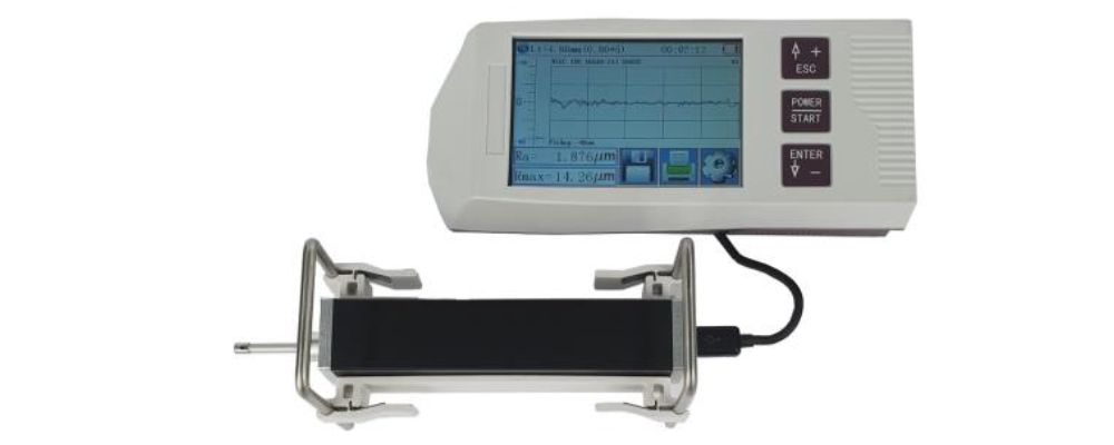
Measurements can be undertaken on suitable flat, cylindrical, recessed and other accessible surfaces using the STARR RTD-210 surface roughness tester. The instrument traces the surface with a diamond-tipped stylus and calculates standard profile parameters such as Ra, Rq, Rz, Rt, Rp, Rv and additional roughness parameters. Results can be assessed against engineering drawings, manufacturing specifications or client-supplied acceptance criteria.
The service is suitable for manufacturing quality control, component verification, condition assessment and failure investigation where surface finish may affect component performance.
Engineering surfaces are not perfectly smooth. Manufacturing processes such as turning, milling, grinding, honing, lapping and polishing leave a characteristic pattern of microscopic peaks and valleys. Surface roughness describes the fine-scale component of this surface texture and is evaluated from a measured profile after the appropriate filtering and evaluation settings are applied.
A stylus profilometer measures vertical deviations as the stylus traverses the surface. The measured profile is processed to separate the roughness component from longer-wavelength form or waviness, allowing recognised roughness parameters to be calculated.
The RTD-210 supports a broad set of profile parameters. The parameter selected for assessment should match the engineering drawing, specification or functional requirement rather than relying on Ra alone.
| Parameter | What it represents | Typical use / interpretation |
| Ra | Arithmetic mean roughness of the roughness profile. | Widely used general indicator of surface finish and manufacturing consistency. |
| Rq | Root mean square roughness of the profile. | More sensitive than Ra to larger profile deviations. |
| Rz | Height-based roughness parameter describing peak-to-valley characteristics over defined profile sections. | Useful where local peak and valley behaviour is important; interpretation must follow the nominated standard. |
| Rt | Total height of the roughness profile over the evaluation length. | Highlights the overall peak-to-valley extreme within the measured trace. |
| Rp | Maximum profile peak height. | Useful where protruding peaks may affect contact, sealing or wear. |
| Rv | Maximum profile valley depth. | Can be relevant to lubrication retention and valley-dominated surfaces. |
| Rsk / Rku | Profile skewness and kurtosis. | Describe the distribution and shape of profile heights where more detailed texture characterisation is required. |
| Rmr and related material-ratio parameters | Material proportion / bearing characteristics of the profile at specified levels. | Useful for functional surfaces such as bearing, sliding and sealing interfaces. |
Additional parameters available from the instrument include R3z, Ry, RSm, RMax, RPc and Rk-family parameters, depending on the selected measurement standard and instrument configuration.
Ra is the most commonly specified roughness parameter, but it averages the profile and can therefore mask isolated peaks or deep valleys. Two surfaces can have similar Ra values while having different functional behaviour. Where sealing, sliding, lubrication, contact fatigue or wear is important, parameters such as Rz, Rt, Rp, Rv or material-ratio parameters may provide more useful information.
For this reason, AECTL reviews the specified parameter and the intended function of the surface before interpreting the result.
Surface roughness measurement should be linked to the drawing or specification that defines the required parameter, tolerance and measurement conditions. The current ISO 21920 series provides the modern framework for profile surface texture specification and interpretation.
ISO 4287 has been withdrawn and replaced by ISO 21920-2. Accordingly, the applicable standard should be confirmed for each project rather than assuming that an older drawing callout and a current ISO 21920 requirement are directly interchangeable.
Where a client supplies a drawing using an older surface texture notation or legacy standard, AECTL can review the nominated requirement and report the measurement basis used.
Reliable surface roughness assessment depends on more than placing the stylus on the component and recording a number. The profile direction, sampling/evaluation length, filter settings, stylus geometry and the surface lay can materially influence the reported result.
For surfaces with a predominant lay, the measurement direction is normally selected to provide a representative profile, commonly across the machining marks unless the drawing or specification requires otherwise. The evaluation length and filtering are selected in accordance with the applicable requirement and the expected roughness range.
Localised scratches, dents, cracks and isolated surface damage should not automatically be treated as roughness. Where these features are relevant to the engineering question, they should be documented and assessed separately from the profile roughness result.
AECTL uses the STARR RTD-210 advanced surface roughness tester. Its separate stylus drive unit provides greater positioning flexibility than a single-body handheld gauge and assists with measurement of surfaces that are difficult to access.
The standard stylus is specified by the supplier as a 90° diamond tip with a 5 µm tip radius and approximately 4 mN stylus force. The suitability of the standard or optional stylus depends on component geometry and the measurement requirement.
Subject to access, geometry and the required traverse length, typical applications include: